

ARDUINO MOTOR SHIELD
 Introduction
What is Arduino?
Use of microcontrollers has increased largely over the recent past in the field of electronics. Components in the microcontroller family are easy to work with due to their flexibility and simple methodologies. Building these into single circuit boards along with all the controller hardware and all the necessary controls such as inputs and outputs, provided a huge hand towards education, especially due the low development cost, and application developers to familiarize new microcontrollers/ processors. The main advantage to any party is that either can move on testing or understanding it’s attributes without a waste of time and energy on developing supporting hardware. Arduino is one of such single-board microcontrollers with open-source hardware and software support of a standard programming language compiler. Since the initiation, a number of versions were introduced until present. ‘Arduino Uno’ was built as the reference model to move forward with advanced USB capability for Arduino platform.
Arduino Uno
‘Arduino Uno’ board is based on ATmega328 and has 20 I/O pins( including 6 PWM outputs and 6 analog inputs). The board is clocked by a 16 MHz ceramic resonator and has a USB connection for power and communication.
What is a shield?
This board has the capability to control outputs to compatible objects or environments over inputs. In order to attach these, a separate circuit board, called a ‘shield’, is built with additional supporting hardware. Those are usually stacked on the Arduino board in a tower.
Controlling motors
There are number of motor types that can be driven by Arduino directly or by other driver ICs. Considering a motor, it shows attributes such as speed, direction of rotation, etc. Software control over these factors is greatly considered in real life applications. Here, control over three types of motors is explained.
- RC servo
- DC motors controlled by a H-bridge
- Stepper motor
Therefore the basic outline is once a shield with supporting hardware for the motors is connected, a simple program written for Arduino could drive them while communication with a computer could control over their attributes.
RC – Servo Motor
RC Servo motors very oftenly mentioned when talking about robotics and automated processes, In DC motors, the load directly affects the speed and current draw, but for practical applications the exact shaft positions are much more important and it must be known with higher accuracy level. Unlike other motors (DC or Stepper) RC servo motors will used for obtain accurate positions such as “shaft moving to 90 degrees or 25 degrees and stop” and motor protocol are universal so the interfacing steps are much easier and well described by many users, which also explain why this is so popular among practical electronic field.

RC Servo motor
Normal DC motor has two wires for the power input (+voltage and Ground supply) and it will continuously rotate when power applied to it, however it will rotate opposite direction when the polarity of the wires are changed. Basically RC servo motors are the same as DC motors but with more mechanical parts and electronic parts, RC servo motors contain 3 wires (+Voltage, Ground and Control) and most servos will run smoothly when the +Voltage in between 5-6 V and it may draw 100 mA to 1 A current depending on motor size. The control wire receives the control signal(PWM pulse) which at about 50 Hz frequency and this pulse deside the servo position.
How servo works
The control PWM pulse (20 ms period) charges a capacitor constantly when the pulse is high (1 ms – 2 ms) after pulse goes to low, charges on the capacitor fed to the output via a buffer amplifier. This effect essentially produced voltage related to the applied duty cycle of PWM pulse.
RC servo motors contain DC motor, gearbox, feedback device (potentiometer), servo control unit and drive circuit.

Block diagram of rc servo motor contents
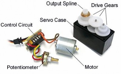
Rc motor contents real parts
- DC motor
This is a normal dc motor and it gives the rotational power to shaft and there are different kind motors available for this (such as brushed motor with core, brushed coreless motor, brushless motors…etc.) but it depends on the RC servo and application.
- Gear Box
This drives the shaft but more importantly torque will be high and the rpm significantly reduced.
- FeedBack device(potentiometer)
This is the servo current posisiton obtaining sensor and the voltage will produce according to the position and after that this value goes to the error amplifier to check wither current position and commanded position are equal.
- Control Unit and Driving circuit
This is the heart of the RC servo motor and this will take care all the steps starting from reading the input PWM signal to output shaft rotation. For more information of what servo contain and their works click here and here.
Give Command to RC servo motor
RC servos can command by giving PWM pulses to control wire. This PWM pulse should have repetitive 20 ms period (50 Hz) pulse with duty cycle variation of 1 ms to 2 ms (some requires range of 0.5 ms to 2.5 ms). The minimum pulse (1 ms duty cycle) will give the minimum servo position (0 degrees – this can be change to 180 degrees by altering coding) and neutral average pulse (1.5 ms) will give the neutral servo position (90 degrees) and finally maximum pulse (2 ms) gives maximum servo position 180 degrees).
So when pulse receives to the control unit it changes the appropriate servo position according to the pulse and servo position will remain same until it receives another command from control unit.
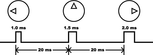
Servo positions for various duty cycles
This is the fritzing diagram for connecting the RC servo motor to the Arduino uno board. Download the fritzing file (rc motor.fzz ).
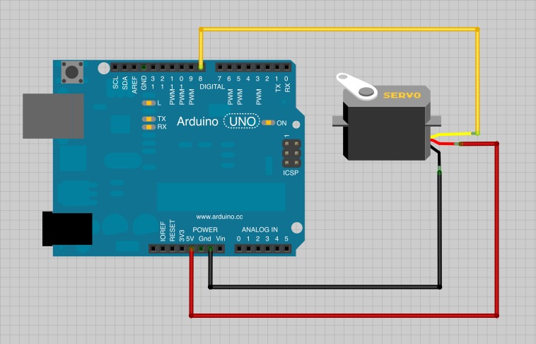
RC servo motor connection diagram
(Click on the image for lager view)
(Click on the image for lager view)
In this experiment serial communication with PC and arduino uno development board was enabled so the RC servo motor positions can control from using terminal (mac), putty (windows) or using serial monitor option in Arduino application.The following code allows the user to input the servo position(0 degree – 180 degree) and full forward and reverse sweep to check whether servo motor working as expect. Download arduino sketch for servo motor form here.(Rc servo sketch)
Stepper Motor
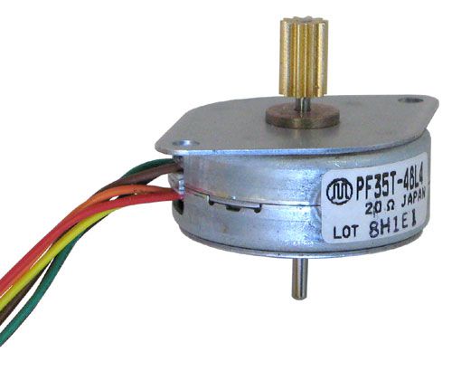
6-wire stepper motor
Stepper motor is a brushless motor that rotates stepwise as the stator consist electromagnets that creates magnetic fields that make the rotor turn. Here, a 4-phase, 6-wire stepper motor (can be run with either Unipolar or Bipolar driver electronics) with 200 steps is considered. This motor is basically able to rotate in different speeds and in the two directions in different step sizes (full steps and half steps).
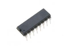
The motor cannot draw enough current from the Arduino Uno board directly. Therefore, power leads of the motor connect to an external power source while the Arduino Uno board connects to other leads through a ULN2803A which consist 8 Darlington transistors that can sink around 500 mA. In this case, pin 13, pin 12, pin 11 and pin 10 of the Arduino board connects to 4 input pins (pin 1, pin 2, pin 3 and pin 4) of the ULN2803A and 4 outputs (pin 18, pin 17, pin 16 and pin 15) are given to the motor.

ULN2803A Darlington array
This is the fritzing diagram for connecting the stepper motor to the Arduino uno board. Download the fritzing file (Stepper motor.fzz).

Stepper motor connection diagram
(Click on the image for lager view)
(Click on the image for lager view)
The provided library originally consist defined functions only for full stepping. Therefore, half step function should be added to the code or the library in order to use it. Basic idea on how the step styles could vary as full steps and half steps is shown below.
Full step drive – Since only one phase is active at a time, power is least consumed.
Full step drive – only one electromagnet is active at a time
(Click on the image for lager view)
(Click on the image for lager view)
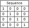
Table of sequence the phases are activated for full step
Half step drive – Stepping resolution is doubled. Since there are steps when 2 adjacent phases are activated, the torque is different at each step and a slight imbalance in windings could result a inaccuracy in positioning unlike in full step drive.
Half step drive – Two electromagnets are activated for a step in between a full step
(Click on the image for lager view)
(Click on the image for lager view)

Table of sequence the phases are activated for half step
Note the 4 LEDs used in the shield, one LED per electromagnet. The LEDs glow according to the sequence the electromagnets are activated. This could help in observing the sequences given in the above tables and decide whether circuitry and the code are correct.
With the above knowledge, extending the code or the library files (Stepper.h and Stepper.cpp) for half stepping can be done very easily. The following links provide library files extended for half stepping:
Click here to download the code that allows the user to choose the step type, direction of rotation, speed and number of steps though the serial monitor.
DC Motor
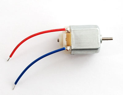
3 V DC motor
The shield is capable of controlling two DC motors. One is controlled via PIN 2,PIN 4 and PIN9 of the Uno and the user can decide the pins to be used for controlling the other motor and make the connections manually. Since the motors consumes current up to 3 A, L298 Full-Bridge driver is used for driving the motors.
L298
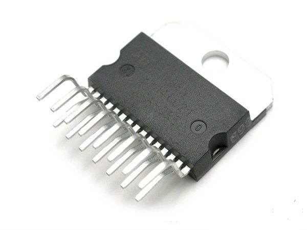
L298 Dual Full-Bridge Driver
L298 Dual Full Bridge driver is capable of driving four high current outputs according to four signal inputs. It can enable or disableOUTPUT 1 and OUTPUT 2 and/or OUTPUT 3 and OUTPUT 4separately with two enable inputs.
L6210
L6210 is a Dual Schottky Diode Bridge having two diode bridges which are used to protect the motor driver from the power generated inside the motor.
L6210 DUAL SCHOTTKY DIODE BRIDGE
In this application, L298 is used to drive two motors independently. INPUT 1 and INPUT 2 are used to set the direction of rotation of the motor. A PWM pulse is applied to ENABLE A to enable the motor as well as to control the speed. In case the user decides to control another motor INPUT 3, INPUT 4 and ENABLE Bpins are used accordingly. CURRENT SENSING A and CURRENT SENSING B pins which can be used to sense the current flowing to the motors are not used for this application and hence grounded.
Note - The speed of a DC motor can be controlled by supplying power to it as a PWM pulse. Since the direction should also be controlled , two PWM pins have to be allocated for each motor.
By driving OUTPUT 1 and OUTPUT 2 by a PWM pulse and its inverted pulse gives the ability to control the speed and direction of a motor with one PWM pulse. But additional hardware has to be introduced to the circuit to invert the pulse and braking the motor is not possible with this method.
Thus in this application, speed control is achieved by enabling the motor (OUTPUT 1 and OUTPUT 2) with a PWM pulse.
Outputs s of L298 have to be connected to the motor through the following diode configuration.
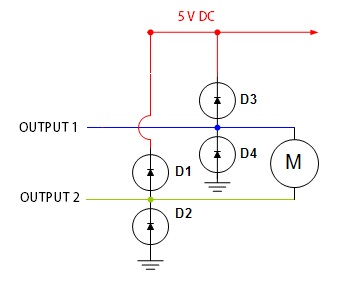
Diode protection configuration
These diodes are used to protect the motor driver from refunded power generated in the motor due to the changing of electric fields.D1 and D3 turn on when the voltage coming from the motor is higher than the voltage of the power source and protect the motor driver from overvoltage. D2 and D4 turn on when the voltage of the motor is below the circuit ground and protect the circuit from undervoltage.
In this project, L6210 having two units of the above diode configuration was used to connect the motor driver to the motor(s).

L6210 Schematic
This is the fritzing diagram for connecting the DC motor to the Arduino uno board. Download the fritzing file (DC motor.fzz).
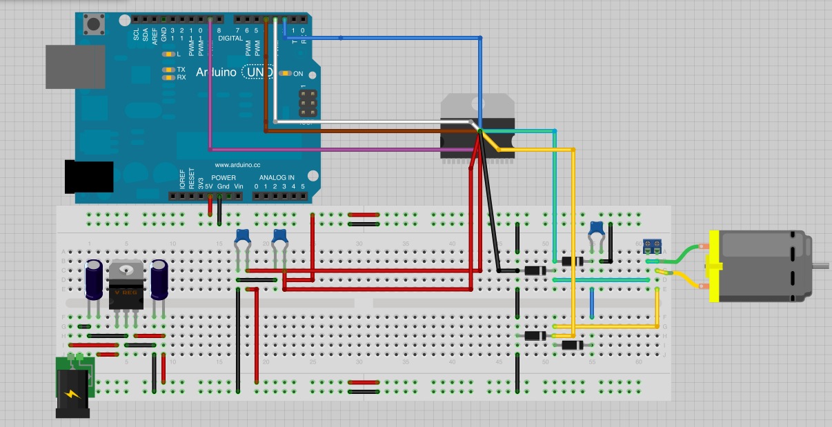
Dc motor connection diagram
(Click on the image for lager view)
(Click on the image for lager view)
Code
A simple terminal program can be used to control the direction, speed and the braking of the motor. The possible motor controls with the INPUT pins are as follows.
| INPUT 1 | INPUT 2 | Result |
| 1 | 0 | Clockwise rotation |
| 0 | 1 | Anti-clockwise rotation |
| 1 | 1 | Brake 1* |
| 0 | 0 | Free run 2* |
1* Brake- Motor comes to a sudden stop
2* Free run- Motor free runs to stop
As motioned, a PWM pulse can be used to control the speed of the motor and with analogWrite function, user can select the 256 speed levels by inserting a integer value between 0 to 255 (with 0 being a stop state and 255 being the maximum speed) to the terminal program.
The DC motor control program provided here is a simple terminal program for communicating with the Arduino board via the serial monitor and is capable of controlling the direction, speed and braking of one DC motor. After uploading the program to the Arduino, open the serial monitor and a menu type application will be available from which the user can control the motor real time.
Hardware Construction
In this post main objective is to crate arduino motor shield which contain rc servo motor, stepper motor and a dc motor. But first all of the above motor constructions were carried out separately and checked whether those are working as expect. Then the all of the above motor schematic diagrams were combine and redrew using “Cadence Orcad Capture Cis 16.5” software to get the final motor shield schematic.
Here is the schematic diagram for final arduino motor shield.

Schematic diagram for motor shield.
(Click on the image for larger view)
(Click on the image for larger view)
Click here to get schematic diagram pdf file (motor shield schematic).
The schematic diagram was transferred to the “Allegro PCB Editor” to design PCB artwork for motor shield. Following figure used as a reference for shield dimensions to design shield which exactly compatible with arduino uno r3 version.
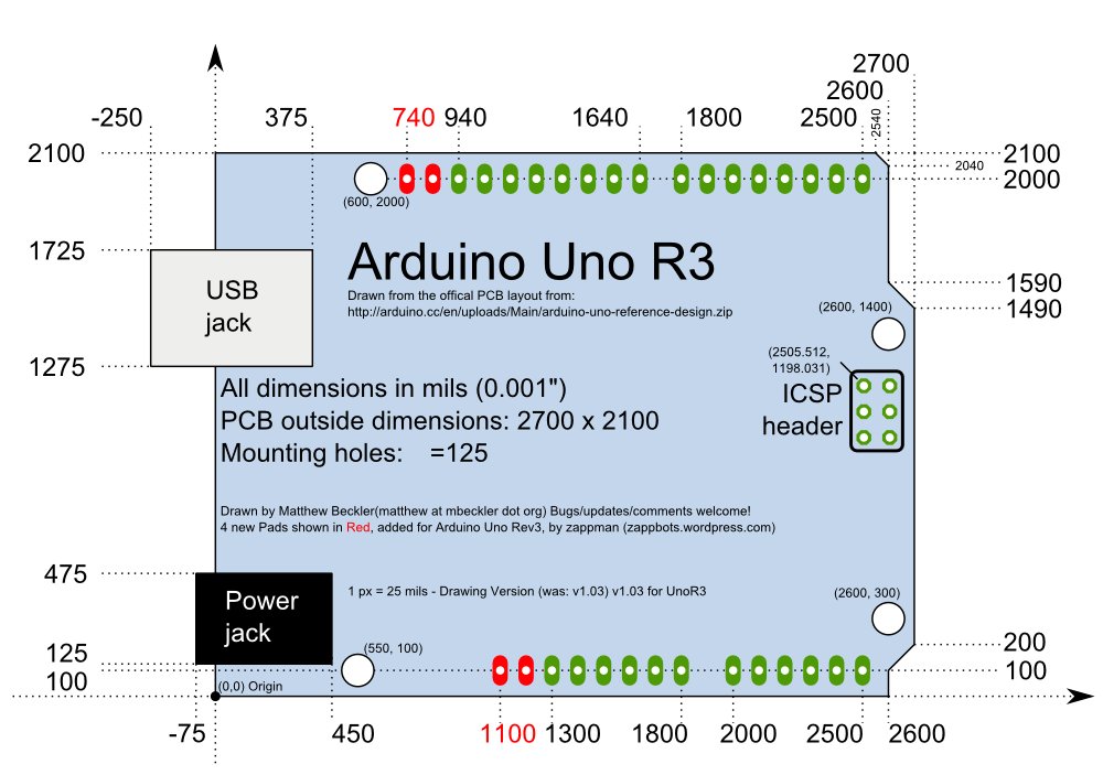
Arduino uno r3 shield dimension reference
(Click on the image for larger view)
(Click on the image for larger view)
- RC servo motor draws current 100 mA – 700 mA from power supply depending on the load, Stepper motor draws 100 mA – 1.7 A depending on the load and Dc motors draws 100 mA – 2 A depending on the load, when all these motors working at the same time cause huge current draw from the supply which cannot handle with arduino uno board, so the separate power supply unit and regulating unit was used to power the shield.
- Also high current traveling PCB track width increased to avoid unnecessary failures. When designing the PCB most of the designing constraints considered except transmission line resistance.
Following figures shows the final PCB design of the motor shield and its 3D view.
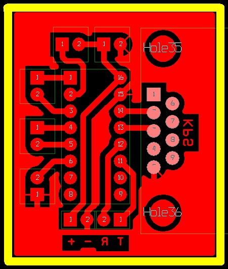
Final PCB diagram
(Click on the image for lager view)
(Click on the image for lager view)
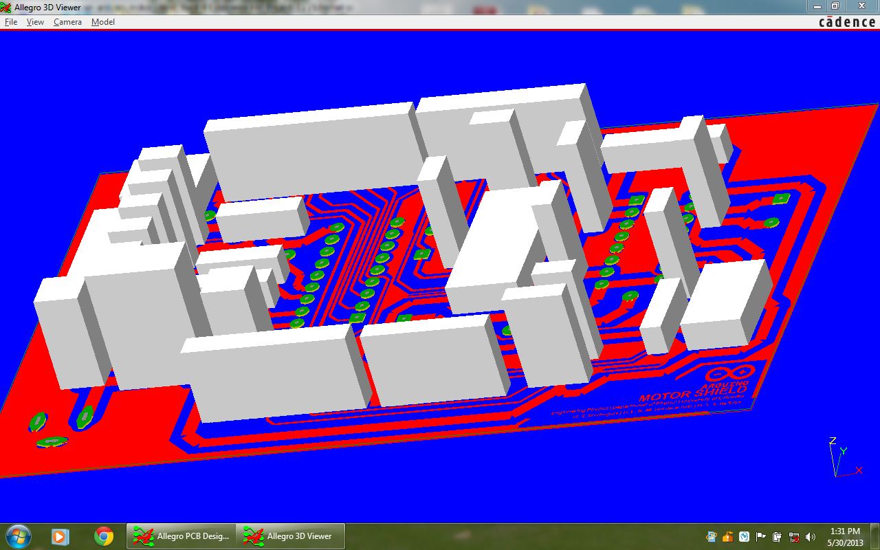
Motor Shield 3D diagram
(Click on the image for lager view)
(Click on the image for lager view)
Following figure shows the final constructed motor shield.
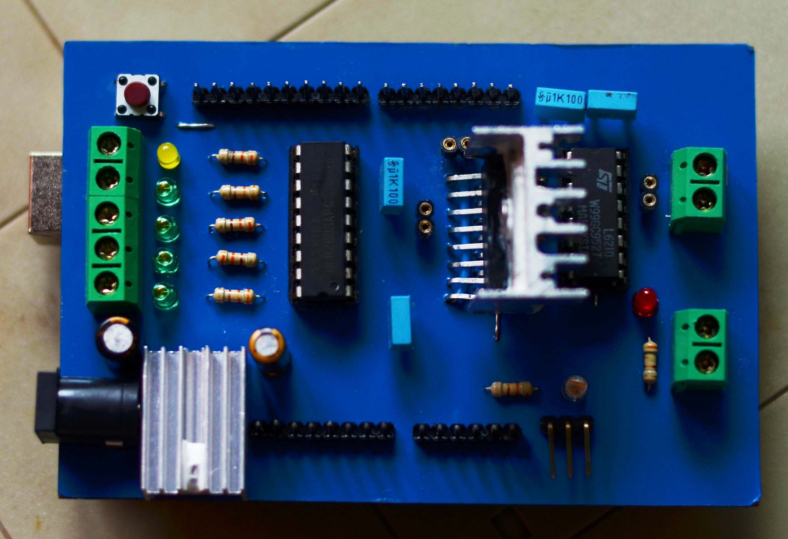
constructed arduino motor shield
(click on image for larger view)
(click on image for larger view)
Bibliography
RC servo motor
- www.instructables.com www.instructables.com, [Online], Available:http://www.instructables.com/id/RC-Quadrotor-Helicopter/step13/Arduino-Demo-PWM-Output/ [9 May 2013].
- www.sparkfun.com www.sparkfun.com, [Online], Available:https://www.sparkfun.com/tutorials/283 [10 May 2013].
- www.sparkfun.com www.sparkfun.com, [Online], Available:https://www.sparkfun.com/tutorials/348.
- Mellis, D.A. (2008) arduino.cc, 11 October, [Online], Available:http://arduino.cc/en/Tutorial/Sweep [10 May 2013].
- pcbheaven.com pcbheaven.com, [Online], Available:http://pcbheaven.com/wikipages/How_RC_Servos_Works/ [9 May 2013].
- pcbheaven.com pcbheaven.com, [Online], Available:http://pcbheaven.com/wikipages/PWM_Modulation/ [9 May 2013].
- teamprincipia.wordpress.com teamprincipia.wordpress.com, [Online], Available:http://teamprincipia.wordpress.com/2007/12/09/arduino-serial-servo-control/ [8 May 2013].
- teamprincipia.wordpress.com teamprincipia.wordpress.com, [Online], Available:http://teamprincipia.wordpress.com/2007/12/08/arduino-pulse-width-modulation/ [10 May 2013].
Stepper motor
- Stepper Motors or Step Motors : Tutorial with Basics, working & types of Stepper Motor – EngineersGarage. 2013. Stepper Motors or Step Motors : Tutorial with Basics, working & types of Stepper Motor – EngineersGarage. [ONLINE] Available at: http://www.engineersgarage.com/articles/stepper-motors?page=6. [Accessed May 2013].
- STEPPER MOTOR, 6-WIRE | AllElectronics.com. 2013. STEPPER MOTOR, 6-WIRE | AllElectronics.com. [ONLINE] Available at:http://www.allelectronics.com/make-a-store/item/SMT-108/STEPPER-MOTOR-6-WIRE/1.html. [Accessed May 2013].
- Freedatasheets.com blog. Datasheet search blog. Semiconductor news. 2013. Freedatasheets.com blog. Datasheet search blog. Semiconductor news. [ONLINE] Available at: http://freedatasheets.com/blog/. [Accessed May 2013].
- Arduino – HomePage . 2013. Arduino – HomePage . [ONLINE] Available at:http://arduino.cc/en/. [Accessed May 2013].
- Arduino – Wikipedia, the free encyclopedia. 2013. Arduino – Wikipedia, the free encyclopedia. [ONLINE] Available at: http://en.wikipedia.org/wiki/Arduino. [Accessed May 2013].
- Arduino Basics: Simple Arduino Serial Communication. 2013. Arduino Basics: Simple Arduino Serial Communication. [ONLINE] Available at:http://arduinobasics.blogspot.com/2012/07/arduino-basics-simple-arduino-serial.html. [Accessed May 2013]
- 6 Wire Motors. 2013. 6 Wire Motors. [ONLINE] Available at:http://pminmo.com/six-wire-motors. [Accessed May 2013].
- Stepperworld Bipolar Tutorial. 2013. Stepperworld Bipolar Tutorial. [ONLINE] Available at: http://www.stepperworld.com/Tutorials/pgBipolarTutorial.htm. [Accessed May 2013].
- Stepper.h (2.9 KB) – arduino – Arduino is an open-source electronics prototyping platform based on flexible, easy-to-use hardware and software. – Google Project Hosting . 2013. Stepper.h (2.9 KB) – arduino – Arduino is an open-source electronics prototyping platform based on flexible, easy-to-use hardware and software. – Google Project Hosting . [ONLINE] Available at:https://code.google.com/p/arduino/issues/attachmentText?id=139&aid=-3349153961204066151&name=Stepper.h&token=4YO6eBAW7SpyOoIMBp59UmeWRDI%3A1367812223322. [Accessed May 2013]
- Stepper.cpp (9.5 KB) – arduino – Arduino is an open-source electronics prototyping platform based on flexible, easy-to-use hardware and software. – Google Project Hosting . 2013. Stepper.cpp (9.5 KB) – arduino – Arduino is an open-source electronics prototyping platform based on flexible, easy-to-use hardware and software. – Google Project Hosting . [ONLINE] Available at:https://code.google.com/p/arduino/issues/attachmentText?id=139&aid=-8315088408709808847&name=Stepper.cpp&token=ftHQ8FK8xSXU1LXDppXDIluB3JU%3A1367812223322. [Accessed May 2013].
DC motor
- www.instructables.com. 2012. DIY Arduino Motor Shield. [ONLINE] Available at:http://www.instructables.com/id/DIY-Arduino-Motor-Shield-L298N-Chip-2-4-Amps-/?ALLSTEPS. [Accessed 27 May 13].
- www.robotroom.com. 2013. DC Motor-Driver H-Bridge Circuit. [ONLINE] Available at:http://www.robotroom.com/HBridge.html. [Accessed 28 May 13].
- http://arduino.cc. 2013. Arduino Motor Shield. [ONLINE] Available at:http://arduino.cc/en/Main/ArduinoMotorShieldR3. [Accessed 27 May 13].
- www.sparkfun.com. 2013. Ardumoto Motor Driver Shield. [ONLINE] Available at:https://www.sparkfun.com/tutorials/195. [Accessed 27 May 13].
Sem comentários:
Enviar um comentário